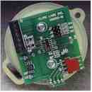
Precision Angular Measurement Systems & Sensors

4 TO 20 mA 4 Wire
ANGLE MEASUREMENT SENSOR
PN 100094-01
The 4 to 20 mA sensor uses our standard ratiometric sensor, and adds a conversion circuit board to give you the most accurate, lowest cost, and most versatile four wire 4 to 20 mA sensor on the market today.

The load resistance between J3.4 and J3.3 should be between 100 and 500 ohms to ensure proper operation.
The voltage will swing from 2 to 10 volts at J3.3 as the output swings from 4 to 20 mA. J3.3 and J3.4 must be allowed to float. A differential input meter is recommended.
The red and green LED will switch at the 12 mA position within 0.3 mA. This indicates that the sensor is level.
To select a range, other than the factory setting, remove the jumper from J5, J6 or J7 and install a select resistor between J3.5 and J3.6 for various output ranges, calculated as shown: R = (556K / desired range) -10K.
For Example:
If the desired range is +/-40 degrees, then the value would be calculated as follows: R = (556K/40) - 10K= 3.9K
Note: Only one jumper of J5, J6, or J7 shall be applied at any one time.
The features of this unique sensor are LED alignment aid, onboard selectable output ranges, infinite remote selectable output ranges and connection for remote LCD readout.
FACTORY JUMPER SETTINGS |
||||
J5 |
J6 |
J7 |
Nom. output |
Tolerance |
| +15 deg | +30 deg | +45 deg | 20.00 mA | 19.7 - 20.3 mA |
| +10 deg | +20 deg | +30 deg | 17.33 mA | 17.0 - 17.6 mA |
| +5 deg | +10 deg | +15 deg | 14.67 mA | 14.4 - 15.0 mA |
| 0 deg | 0 deg | 0 deg | 12.00 mA | 11.7 - 12.3 mA |
| -5 deg | -10 deg | -15 deg | 9.33 mA | 9.0 - 9.6 mA |
| -10 deg | -20 deg | -30 deg | 6.67 mA | 6.4 - 7.0 mA |
| -15 deg | -30 deg | -45 deg | 4.00 mA | 3.7 - 4.3 mA |
PIN ASSIGNMENTS |
|
Pin designations |
Description/Function |
| J4.1 | 12 Vdc Regulated (out) |
| J4.2 | System Ground (out) |
| J4.3 | Reference(out) |
| J4.4 | Signal (out) |
| J3.1 | 24 Volt High (in) |
| J3.2 | 24 Volt Low (in) |
| J3.3 | 4-20 mA Low (out) |
| J3.4 | 4-20 mA High (out) |
| J3.5 | Optional Scale Resistor (in) |
| J3.6 | Optional Scale Resistor (in) |
