Precision Angular Measurement Systems & Sensors
4 TO 20 mA 2 Wire
ANGLE MEASUREMENT SENSOR
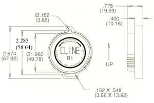
P/N 100412-01


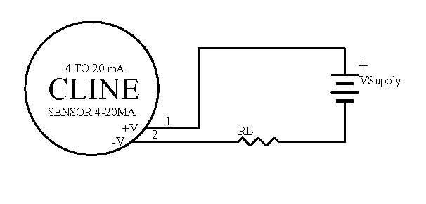
The voltage across the sensor must be between 8V and 36.0V. The supply polarity is diode protected but J1.1 must be plus and J1.2 must be minus to operatate correctly.
The equation to determine the maximum load resistance for RL is as follows: RL max = (Vsupply - 8) / 0.02
Example: Maximum load resistance at 24 volt supply is (24 - 8) / 0.02 = 800 ohms
To determine the load resistance RL for a single sided 0-10 volt meter that reads the voltage across the load resistor. 10 volts / .020 mA = 500 ohm resistance. The supply voltage VSupply must be greater than 18 volts (10 across the resistor plus 8 across the sensor) and less than 36 volts.
For best performance operate the sensor as follows: Null (rotate sensor in slot) is set at 13mA, -45 arc-degress is 5mA, and +45 arc-degrees is 21mA. The sensor to 4-20 mA converter becomes non-linear below 5mA.
General Specifications:
|
|
PIN ASSIGNMENTS |
|
Pin designations |
Description/Function |
| J1.1 | Supply Voltage High (in) |
| J1.2 | Supplay Voltage Low (in) |
